
Electric Rotary or Selector Valve Application Examples
Electric rotary or selector valve is a stepper motor driven fluid handling valve designed for automated fluidics applications. The precise rotary valve provides automated routing of fluidic volumes for aggressive fluids. We offer a cost-effective solution to build your fluid handling module in the instrument design or laboratory experiments. 6-way, 8-way, 10-way, 12-way and 16-way electric rotary valves are available for order. With small dead volumes and accurate positioning systems, they are widely used in analytical instruments. A variety of typical applications are included in precision fluid handling but not limited to:
- HPLC
- In vitro diagnostics (IVD)
- Biological sample preparation and distribution
- Sample injection or selection
- Reagent recirculation system
- Microfluidics sample delivery or perfusion system
- Automatic reagent delivery
- High speed sample enrichment
- Column back flushing
- Flow cytometry or chemistry analyzer
- Mass spectrometers
- Elemental analyzers
- Analytical instruments
1.1 Technical Parameters
| Configuration | 6/8/10- Port | 12- Port | 16- Port |
| Orifice size (mm) | 1.2 | 1.0 | 1.0 |
| Internal volume | 27.5uL | 22.43uL | 33.68uL |
| Dead volume | 5.4uL | 6.1uL | 10.4uL |
| Wetted material | PCTFE, Sapphire | ||
| Pressure rating | 0- 1.0MPa (air); 0 -1.6MPa (DI water) | ||
| Fluid temperature | 0 -150 degree C | ||
| Fluidic Interface | 1/4''-28 UNF female thread | ||
| Switching time | 280 -450ms | ||
| Communication | RS232/RS485/CAN | ||
| Baud rate | See details in user manual | ||
| Address and Parameter | Via communication | ||
| Power supply | 24VDC/3A | ||
| Max. power | 60W | ||
| Environment temperature | -10-50 °C | ||
| Working humidity | ≤80% (relative humidity, non-condensing) | ||
| Dimension (L x W x H) | 60mm x 65mm x 180mm | ||
| Net weight (kg) | 0.75 -1.0 Kg | ||
1.2 Flow Port Configuration
The flow port configuration is shown below. The central port of the valve is the common port and the valve can switch to any specific port by the rotor. The reset direction is counterclockwise. After reset, the rotor sot is between the port 1 and the maximum port number. The center port and other ports are disconnected to ensure no fluid leakage.

Figure 1. Flow port configuration

Figure 2. Electrical rotary valve selection guide
1.3 Mechanical Dimensions and Mounting Location
The cross-section dimension of the electrical rotary valve and the mounting hole locations are shown in the figure below.

Figure 3. Rotary valve dimension and mounting locations
1.4 Communication Protocol (see the user manual for details)
1.5 Application Examples
1.5.1 Multi-Channel Reagent Distribution System
Components and equipment are required as the follows. The schematic is shown in Figure 13.
- Valve reset position: it is located in between position 1 and 10
- Syringe pump
- Two-way solenoid valve: normally closed
- Glass syringes
- DI water reservoir
- Inline pressure transducer
- Waste container
- Reagent containers
- Tubing and fittings

Reagent Priming Steps (for example)
- Electrical rotary valve reset, and the 2-way solenoid valve turned on
- Syringe pump withdraws DI water from water reservoir (aspirated water volume larger than liquid reservoir loop)
- 2-way solenoid valve turned off and rotary valve switches its position to port 2
- Syringe pump is homed and dispenses all DI water to waste container through port 2
- Rotary valve switches its position to port 3 and the syringe pump aspirates reagent 1 through port 3 to the liquid reservoir loop
- Rotary valve switches its position to port 2 and home the syringe pump
- Rotary valve switches its position to port 10. The syringe pump aspirate 1mL air through port 10
- Rotary valve switches its position to port 3 and dispense 100uL air
- Rotary valve switches back to port 2 and dispense all reagent
1.5.2 Microfluidics Sample Selection and Delivery Recirculation System
Components and equipment are required as the follows. The schematic is shown in Figure 14.
- Sample/buffer solution reservoir
- Pressure controller (8- channel compressed air; 2-channel vacuum)
- Electrical rotary/select valves
- Microfluidic chips (droplet generator or cell sorter)
- Inline filter
- Liquid flow sensor
- Dino-lite microscope
- Waste container
The real-time flow rate is monitored by the liquid flow sensor (ranging from a few microliters to 5mL/min depending on the application requirements). The analog signal from the flow sensor via RS232 or RS485 or digital signal via I2C provides feedback to the pressure controller and forms a closed loop control to deliver desired flow rates of samples or reagents. The electrical rotary valve can switch to any ports and select different reagents or buffer solutions. The generated droplets in microfluidic chip can be imaged and analyzed through regular microscope, such as Dino-Lite microscope or fluorescence microscope. Vacuum pressure is applied to the waste collection container. Finally, the waste is collected to the waste container.

Figure 5 Schematic of microfluidics sample selection and delivery with rotary valve

Related Articles

Practical Fluidic Interface Guide for Electric Rotary Valves in Laboratory Automation
The electric rotary or multi-channel switching valve is a stepper motor-driven fluid handling valve designed for automated fluidics applications. This precise rotary valve automates the routing of fluidic volumes, allowing for the handling of aggressive fluids and switching flow directions as needed. For instance, in a multi-channel distribution valve, a common central port connects the stator and rotator, enabling the switching of flow direction between different ports with a rapid response time of less than 120ms for adjacent ports. This switching valve can communicate through RS-232, RS-485, or CAN interfaces, allowing for multi-valve arrangements of up to 15 valves in one group. See Figure 1 for the wiring instruction. It supports group control and individual addressing, making it versatile for various automation needs. The wetted materials in the flow path are PCTFE/Sapphire and can be customized upon request.
Related Products

Syringe Pump Programmable, Flow Rate 0.138 µL/min - 52.94 mL/min, Infusion/Withdrawal, TJP-3A/W0109-1B
This programmable syringe pump (TJP-3A/W0109-1B) is a single channel micro-syringe pump has infusi..
$2,504.20

Electrical Rotary Valve, 16 Ports, Orifice size 1.0 mm, Max. Pressure 1.5 MPa
Electric rotary or selector valve is a stepper motor driven fluid handling valve designed for fluid ..
$1,506.25
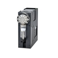
Industrial Syringe Pump ASP-SY01 Integrated with Electrical Rotary Valve, Max Stroke 30 mm
ASP-SY-01 is a compact OEM pump module designed to handle precision liquid handling application. The..
$0.00
Tags Sample Preparation, Drug Delivery, Reagent Injection, Cell Culture, Point-of-care testing (POCT), In vitro diagnostics (IVD)